Introduction
Meshing is an aspect of finite element analysis that sometimes gets overlooked by FE analysts, particularly those with the luxury of comparatively small models and/or powerful computing resources available. As a junior engineer, I rarely went beyond the “tet and forget” approach, since it is very easy to do in modern software packages and I had more than enough resources at my disposal to solve my models. Once the models started getting larger however, I had to start paying more attention to my meshing strategy to avoid unreasonable solving times.
So what is the “best” approach?
The short, if unhelpful answer, is: “It depends on your application”. Rather than listing all of those (even if I could), I will focus on a few key principles that apply to all FEA models:
- Efficient meshes take time to build (usually).
- The mesh only needs to be good enough to answer your question.
- More nodes/elements require more resources to solve.
Finding a good balance between these considerations is entirely dependent on the time and hardware available. It hardly makes sense to spend an extra day on a mesh that takes less than an hour to solve. Nor is it appropriate to build a very coarse model that solves quickly, when a detailed hot-spot weld stress analysis is needed.
FEA Elements
Deciding which element types to use is half the battle. In broad terms, the more nodes in an element, the more degrees of freedom it can represent and the longer it takes to solve. The diagram below lists some of the typical element types, in order of increasing computational expense.
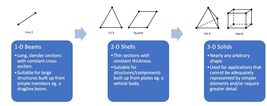
The linear shell and solid element types shown above also have quadratic counterparts i.e. nodes on the sides as well as the corners. These have the benefit of increasing the number of degrees of freedom in the model with the same number of elements. Generally, it is acceptable to stick with the simpler linear elements, with one important exception: Avoid using linear tetrahedral (Tet 4) elements if possible! Simply put, these elements are too numerically stiff to be practical for most applications. Your choice is between a significant underprediction of strain, or to use a lot of elements to prevent them from “locking up”.
Some pretty pictures to prove the point
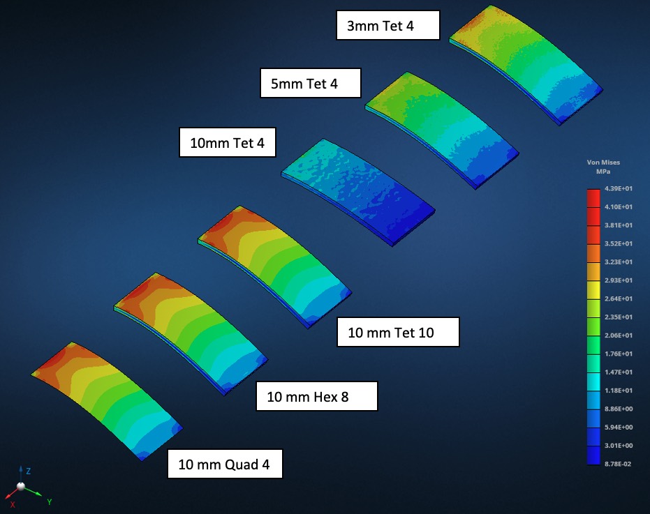
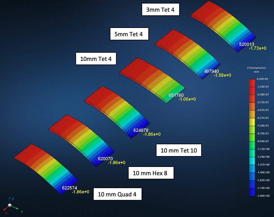
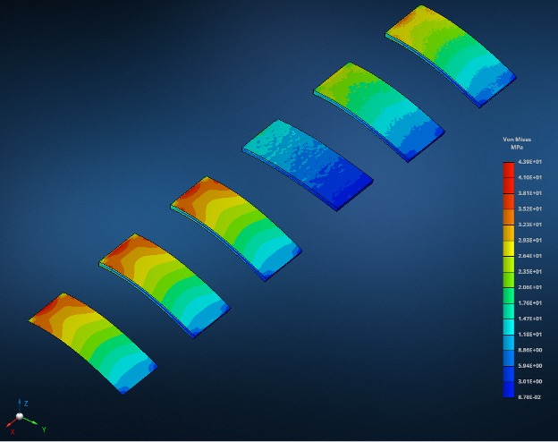
Consider the simple case of a plate in bending. Here I have meshed the same 500x250x20 mm plate with a few different element types and sizes.
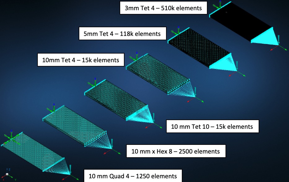
Notice how the linear shell (Quad 4), linear hexagonal (Hex 8) and quadratic tetrahedral (Tet 10) meshes produce very similar stress distributions, whereas the Tet 4 meshes need to be much finer to even start approaching the same results.
The same applies for the displacement, where 34 times more Tet 4 elements are required to get a deflection result that is within 90% of what the Tet 10 mesh predicted!
Conclusion
This is by no means an exhaustive introduction to the world of FEA, but hopefully it gives you a few pointers for approaching meshing. In summary, before starting with an FEA model consider the following:
- What level of detail is needed?
- Which element types are suitable to represent the geometry?
- How much time is available?
- How much computer memory is available?


0 Comments