

Situations arise where the service life of tanks used at plants and storage facilities is increased due to operational requirements. Then there are situations where the design life of tanks is less than the service life because the intention at the design phase was to replace these tanks. In both these cases, and for many other reasons, the need arises to use a tank beyond its design life. Condition-based extension of tank usage beyond its design life as a well-known approach applied by industry. The condition of a tank from structural integrity point of view is dependent on:
- Shell thickness.
- Cracks – their locations, sizes, and directions.
- Presence of pit-like corrosion.
- Construction quality.
Phased-array ultrasonic testing of tank shell superstructures provide a useful distribution of the remaining thickness, and the presence of crack-like indications. Size and location of zones where the shell has thinned to below minimum values are identified.
For this blog Investmech assumes that the tank design complies with the applicable design codes and/or standards and was not considered.
1.1 Thickness
Consequences associated with reduction in shell thickness is buckling (for those members in compression) and plastic collapse. Due to the relatively low maximum allowable design strength prescribed by the codes and standards, it is unlikely that a tank will fail in plastic collapse, except for example where groove-welds under tension are not complete penetration butt joints. The risk of tank buckling increases with increased local thinning zone thickness loss and size. Combined with increased loading on the top of above-ground storage tanks, buckling of tanks is a possibility and must be analysed in the design phase and as part of the condition-based maintenance programme.
1.2 Cracks
Fracture mechanics is the theory applied to cases where cracks are identified. The critical crack size is calculated (governed by plastic collapse or fracture) and the number of cycles estimated for crack propagation from identified size to critical crack size. A fracture control programme (basically crack size vs. time or cycles) is then used to define the longest inspection interval over the remaining life. Codes and standards provide formulae for the calculation of these inspection intervals. Investmech calculates and applies fracture control programmes on a wide range of structures and machinery.
1.3 Pit-like corrosion
Pit-like corrosion causes stress concentrations that create the conditions for crack initiation. Fatigue codes like BS 7608 recommends 0 MPa as the cut-off limit for unprotected surfaces exposed to corrosion in seawater. Low stress ranges can therefore result in crack initiation – it is just a matter of time. This is one reason for industry to apply expensive coatings on external surfaces and where applicable, linings on the wear side, of tanks. Pit-like corrosion must therefore be prevented at all costs to ensure the durability of a tank.
1.4 Construction Quality
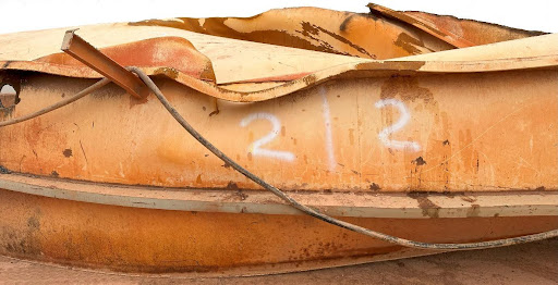
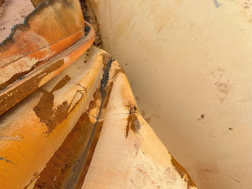
Investmech has investigated tank collapses where the root cause is quality of construction. Investmech assessed cases where the meridional (longitudinal) groove-welds on an above-ground storage tank were not complete penetration butt-joints as prescribed by the codes. After some thinning of the shell the meridional weld failed under the tensile circumferential stress. The shell plates lost their buckling resistance, followed by collapse of the tank. Due to interconnectivity to other plant infrastructure, they were also damaged during the event. Investmech is continuously involved as third-party in the manufacturing quality control process of tanks and other plant infrastructure.
1.5 Standards
International standards are used in the design and construction of tanks and include but are not limited to API & ASME codes and, BS and ISO standards. Not all these codes and standards require fatigue analysis on for example CIL (combination in leach) and similar tanks, and shell and other strengthening member dimensions are determined based on static calculations alone.
Uneven wear and corrosion driven thinning of tank shells result in stresses that could exceed the maximum allowed design stress prescribed by the applicable codes and can result in crack initiation or yielding. This is the reason for wear allowances on tanks.
1.6 Fracture Mechanics
Where a tank has cracked, fracture mechanics principles are applied to calculate critical crack sizes (based on plastic collapse or fracture, whichever occurs first). Fracture control programs are then compiled that can be used to safely monitor the crack propagation whilst the necessary repairs are scheduled.
1.7 Buckling
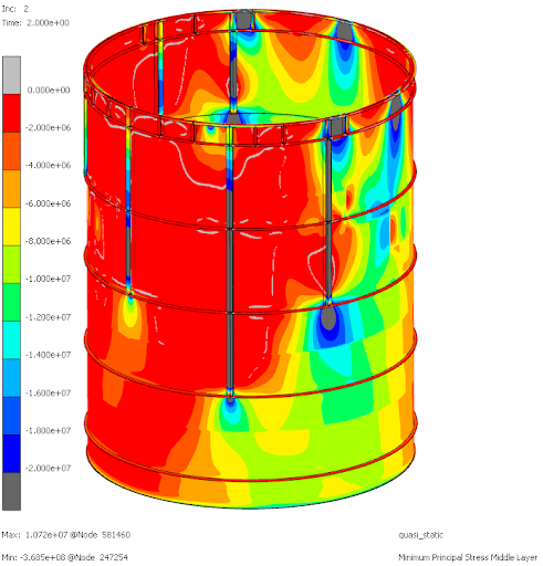
The maximum amount of local thinning that result in failure by yielding or buckling is calculated from real life simulation of the tank construction and its external loading. Probability of failure driven factors are incorporated in the analysis to determine the tank limitations. Some code formulae and maximum allowable strengths are conservative and do not require a buckling analysis on above-ground vertical tanks (like CIL tanks). Investmech performs finite element analysis based buckling assessment under all circumstances.
1.8 Recommendations and solutions
Knowing where and how the tank is likely to fail, repair scenarios are compared to determine the most feasible solution. On final approval the client normally implements the solution under Investmech’s third party quality control over the process.
Procedures (welding procedure specifications, welding procedures, sequence of strengthening) are essential contents in the data book. Investmech generate or review applicable procedures against applicable design and construction codes & standards to ensure the quality and durability of the tank. Investmech then ensure compliance of the manufactured product with the applicable codes & standards.
Surface protection of tanks exposed to corrosive environments cannot be overemphasized. In cases of excessive wear on the inside, wear resistant liners is a feasible solution.
Stiffening rings are installed to resist side loads on the tanks (wind, etc.). To space stiffening rings close enough to resist local buckling of torn meridional welds is expensive.
Local stiffening of severely thinned zones can be a feasible solution. The pressure vessel codes provide useful formulae for the design of stiffening plates for local stiffening of tanks.
Vertical stiffeners can be installed to resist the vertical loads on the top of the tank. Where the top of the tanks will be heavily loaded by other plant requirements, putting the platform above the tank on its own supports can be a feasible solution.
Reinforcement with glass fibre reinforced plastic has been analysed on several sizes above-ground CIL tanks by Investmech. Investmech prepared the quality control plan with applicable procedures and instruction and performed quality control over the implementation of this solution to tanks.
In most cases Investmech uses finite element analysis stress distribution calculations in tanks. The advantage is that the tank superstructure can be simulated in the condition that it is (with local thinning, incomplete penetration where complete penetration is required, cracks, etc.). Any stiffening and/or reinforcement can be included in the simulation to assist with finding the most viable solution.
0 Comments